The Fender (Parsons/Green) B-Bender is designed and manufactured to provide decades of trouble free service when it is properly adjusted and installed. These installation instructions assume that you have the proper equipment, skill and professional experience necessary to install this B-Bender.
Please read the instructions carefully. If you decide you would prefer to have Gene Parsons at the StringBender Custom Shop do the installation he can be contacted as follows:
Email: parsons@stringbender.com
Phone: (707) 964-8146.
Disclaimer: StringBender, Incorporated, Fender Musical Instrument Corporation and the StringBender Custom Shop will not be responsible in any way for damage occurring to a guitar as a result of improper installation of a Fender (Parsons/Green) B-Bender.
TOOLS:
- Measuring scale or rule
- Soft hammer
- Scribe
- Grease pencil
- Drill Press
- 15/16" inch diameter 'Forstner' (or other suitable) drill bit
- Router with 3/8" to 1/2" straight type router bit and template following guide. (The diameter of the router guide should be no more the 1/8" larger than the diameter of the router bit.)
- Routing Box. (This optional but handy device holds the guitar body and template in place while routing.)
STEP ONE: LOCATE THE CENTER FOR THE 'STRING PULLER TOWER'
Note: This is an extremely important step because the function of the Fender B-Bender and ultimate success of the installation depends directly on the proper location of the 15/16" hole that must be
drilled in the guitar body to accept the 'String Pulling Tower'.
Procedure:
- Lay the guitar on its back with the neck extending towards the left.
- Remove the pick guard.
- Use a grease pencil to draw a line longitudinally, exactly down the center of the guitar body. (See Photo A and Full Size Drawing & Layout Plan). This will be your baseline for reference and will be called the 'Body Center Line'.
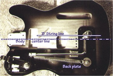
Photo A : Center line and 'B' String line
- Mark a line parallel with the 'Body Center Line' extending through the center of the B string ferrule hole. This will be called the 'B String Line'.
- Lay the Fender B-Bender on top of the guitar as shown in photo A and position it so that these four criteria are satisfied:
- - The 'String Pulling Tower' is centered directly over the 'B String Line' (see Photo A).
- - The long, straight edge of the Fender B-Bender 'Back Plate' is parallel with the 'Body Center Line.' Measure with a scale to be certain as shown in Photo C.
- - The clearance between the inside edge of the 'Strap Lever' and the edge of the guitar bout is no less than 1/8" as shown in Photo B.
- - The Fender B-Bender 'Back Plate' is positioned so that its outer edges are aligned as closely as possible to being concentric with the outer edges of the guitar body.
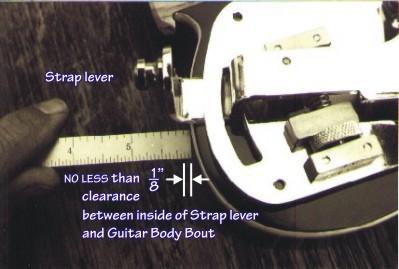
Photo B : Strap lever clearance

Photo C : String pulling tower alignment
- With the Fender B-Bender still laying on top of the guitar body and the four criteria satisfied, measure from the center of the B string ferrule hole to the edge of the 'String Pulling Tower' (along the B String Line) as shown in Photo D. Add to this measurement half the distance across the width of the base of the 'String Pulling Tower' (29/64"). The sum of these two measurements is the distance to the center of the 15/16" diameter hole you will bore for the 'String Pulling Tower'.
Note: Be sure that the Fender B-Bender 'Back Plate' will not interfere with the String Ferrules.
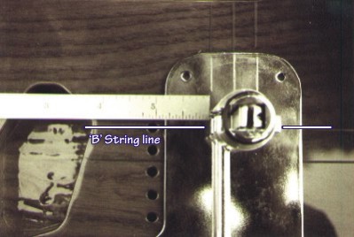
Photo D : Measuring for the 15/16" hole center
- Remove the Fender B-Bender from the face of the guitar and carefully mark the 15/16" hole center point with the grease pencil. When you have double checked your measurements and are completely certain of the location of the 15/16" hole to be bored, mark the center with a scribe.
STEP TWO: BORE 15/16" HOLE
- Set drill press table so that it is flat/horizontal. (See photo E)
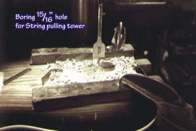
Photo E : Boring the 15/16" hole
- Clamp and align guitar body in drill press using padded blocks or other suitable protective devices.
- Using a sharp, 15/16" diameter 'Forstner' (or other suitable) drill bit, drill the 15/16" hole for the 'String Pulling Tower'.
4. Remove guitar body from drill press.
STEP THREE: MAKE A ROUTING TEMPLATE
We use 1/8" clear Plexiglas for our routing templates and a 'Routing Box' (See photo F). You may have your own preferences or have access to a 'Pin Router' or CNC routing machine. All the better. In any case, be sure that you produce a routed area that is not smaller than shown on the template included with the Fender B-Bender. A fraction oversize may be acceptable but not undersize.
Photo F : Routing box and clear template ready for routing
STEP FOUR: ROUTING
- Study the 'Full Size Drawing, Layout & Rout Plans'. Note the relationships and alignment between the rout and the 'Back Plate'. There must be enough wood left after routing to accept the 'Back Plate' mounting screws. The 'Fender B-Bender Back Plate Outline' used in conjunction with the 'Routing Template' and 'Full Size Drawings, Layout & Rout Plan' will enable you to determine the proper location of the rout.
- Rout the main cavity to a depth of 7/8" as indicated in the 'Full Size Drawing, Layout & Rout Plans.'
- Rout the double crosshatched area indicated in the 'Full Size Drawing, Layout & Rout Plans' to a depth of 1-1/8". (See photo G)
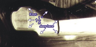
Photo G : Area for deeper routing
- The area around the 15/16" diameter hole for the 'String Pulling Tower' needs to be routed to a depth of 1-5/16" and should be approximately 1-1/8" in diameter. (It doesn't have to be exactly
1-1/8" as it is only for clearance but it must not be smaller than 1-1/8". Please refer to the 'Full Size Drawing, Layout & Rout Plans' and see Photo H)
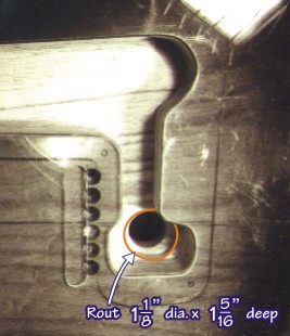
Photo H : Area for deeper routing
STEP FIVE: INSTALL FERRULE RING
The large ''Ferrule ring' that is included with the Fender B-Bender should be carefully driven with a soft hammer into the 15/16" 'String Pulling Tower' hole from the face side of the guitar. (See photo I)
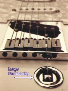
Photo I : Ferrule ring
STEP SIX: INSTALL FENDER B-BENDER
- Clean up any rough areas in the routed cavity.
- From the back of the guitar, insert the 'String Pulling Tower' into the hole and carefully press the Fender B-Bender down into the routed cavity. (A little grease on the String Pulling Tower's O-ring may aid the top of the Tower to enter into the 'Ferrule Ring'.)
- Check that there is enough clearance for the Fender B-Bender to go all the way down with the 'Back Plate' flat against the back of the guitar body and still have room for the 'Strap Lever' to work all the
way up and down in its slot in the 'Back Plate'. (Adjust the 'Tuning Wheel' to allow for maximum 'Strap Lever' motion). If there is not enough room for the Fender B-Bender to be pressed all the way down while at the same time aligning with the 'Body Center Line' a little more material will have to be taken out of the routed cavity where there is interference.
- When all is clear for the Fender B-Bender to be installed into it's routed cavity, the holes for the mounting screws can be pilot drilled and the 'Back Plate' fastening screws inserted.
- With the Fender B-Bender secured by it's fastening screws, check again to be sure the 'Strap Lever' will work all the way up and down smoothly in it's slot.
- If everything looks good at this point, remove the Fender B-Bender and apply flat black paint the area of the routed cavity that shows through the open slot where the 'Strap Lever' protrudes out of the 'Back Plate'.
- Re-install the Fender B-Bender.
Note: A standard Telecaster body is 1-3/4" thick. If the guitar body that the Fender B-Bender is being installed into is thicker than a standard Telecaster body, a 3/16" (inner diameter) spacer washers can be inserted between the base of the 'String Pulling Tower' and the 'Back Plate'. This will position the 'String Pulling Tower' and its pendulum a little farther/higher into the 'Ferrule Ring'.
STEP SEVEN: CUT SLOT FOR 'B' STRING IN BRIDGE PLATE
TOOLS:
- 3/32" to 1/8" round file OR Vertical milling machine with 1/8" end mill
- Grease pencil
- Measuring scale
- If your bridge is the flat saddle style with the intonation screws in line with the strings you will also need a threading tap and tap drill that corresponds to the size of the intonation screw.
Procedure for the three or six saddle traditional bridge:
- Make a mark with grease pencil or indelible pen, with the strings and bridge still
in place, on the back lip of the bridge directly in line with the 'B' STRING LINE.
This mark will indicate where you must make a slot in the bridge plate lip to allow a path the for 'B' string to extend from the String Pulling Tower (or the Pull Hub for the Classic B-Bender as shown) to the bridge.
- Remove the strings and free the pick-up from the bridge plate. Remove the bridge plate from the guitar. If you are going to use a file to cut the slot you will also need to remove the 'B' saddle.
- File or mill a slot, centered on the mark, to a depth of 5/16" (plus or minus 1/16" depending on the neck angle and bridge height).
Procedure for the bridges with flat saddles and intonation screws in line with strings:
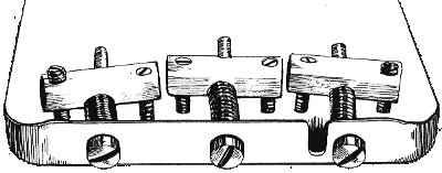
- File or mill slot for 'B' string in the lip of the bridge plate right where the intonation screw is located. The threaded center portion of the saddle needs to be milled or filed out. Leave 1/32" ledge on the bottom of the slot to keep the saddle strong and rigid.
- Re-drill and re-tap into the leg of the saddle that is to the right as you are looking at the guitar with the neck extending up.
- Bore a new hole for the intonation screw just to the right of the slot in the lip of the bridge plate.
Flat style bridges with machining already done are available from StringBender Custom Shop.
David Matlin of Matlin Guitars in Mendocino, California designed the Routing Box shown below. The drawing shows a Routing Box with a Classic B-Bender Routing Template. It is important if you planning to install a B-Bender that you have an effective system for keeping the relationship between the routing template and the guitar. If this is not something you are adept at you may want to have Gene Parsons at the StringBender Custom Shop do your Fender B-Bender installation.